
Audio
Power Amplifier Power Rating Mysteries Explained
(Once and For All!)
Rev (F)
(c)
2000-2007 By Joe Roberts
Why this article?
I receive quite a number of questions via e-mail regarding power ratings on amplifiers as well as many questions on what clipping is and why it can be bad for speakers. Other questions include things like "What is instantaneous power, peak power, RMS power?" "What is a crest factor and how does it relate to headroom?" I also sense that there is a fair amount of mis-information circulating within the consumer (and sometimes the pro audio) audio community. When I was a teen just learning all of this stuff, there was no one I knew that really knew this material... there was no one I could ask questions of. It took me years to finally figure it all out. This article will attempt to make it easy for the reader to clear up the mysteries of power ratings dealing with audio power amplifiers. This article is quite extensive and will cover many topics in a fair amount of detail. Plots and graphs will be used to illustrate various concepts. There is necessarily some math in this article, but please do not be too frightened by this. I will try to keep things as readable as possible!
Assumptions: For most of this article some assumptions must be made. For the power amplifier we will consider, the power supply will have "rails" that do not sag with load, and we will treat speaker loads as purely resistive (otherwise things will get too complicated too early). Later sections will cover "real world" amplifiers and what performance can suffer as a result.
Amplifier Basics: Before we explore what power ratings are all about we need to cover some basics about amplifiers. The first thing to understand is that an amplifier is a device that takes a weak electrical signal and makes it stronger. In the case of an audio amplifier we wish to take the weak signal from the source (CD player, tuner, tape deck, etc.) and make it strong enough to drive one or more loudspeakers. The ideal amplifier will do nothing to the input signal other than make it stronger. In a real world amplifier, the signal does get stronger (amplified) but because no amplifier is perfect there are other undesired characteristics that appear in the output signal (noise and distortion). In the very best amplifiers these undesired characteristics are quite small (but they are not zero). Also, all amplifiers have limitations as to how much power they can put out. If you try to get more power out of an amplifier than it was designed to provide, the output will rapidly become very distorted because the amplifier will go into a condition commonly referred to as "clipping".
For this article to make sense, the reader must have at least a minimal knowledge of the basic topology of an audio amplifier. There are a number of classes of amplifiers used for audio (such as A, B, AB, D, H and G to name some of the more common ones). The class of an amplifier refers to the method in which the components within operate (you may sometimes hear this referred to the "bias" type of the amplifier). We will discuss the most common form used for audio amplifiers; that is, class AB. The various classes used for amplifier design determine the level of distortion, efficiency, heat dissipation, etc. You do not need an understanding of the details of the class of an amplifier to gain an understanding of power ratings. Consider the diagram below:
Figure 1. High Level Block Diagram of Class AB Amplifier
Figure 1 shows a very high level diagram of the internal workings of a typical class AB audio power amplifier. Notice that there is a power supply; this component converts the 120 VAC voltage from a wall socket into a DC voltage. The power supply creates two DC voltages, equal in magnitude but opposite in polarity. These two voltages are often referred to as the rails of the power supply. We will refer to this term often within this article! Note that the power supply rails are fed directly to the output stage of the amplifier. The amplifier also has an input stage; this is the portion of the amp that receives and conditions the input signal (it is where the level controls would be located). It too receives its operating power from the power supply, but input stages of amplifiers often use a lower voltage that is more tightly regulated. Low level circuits at the input stage are often of class A design in order to maintain the highest possible fidelity. The output stage of the amplifier is what drives the speaker(s).
Now let us consider the power supply once again. Specifically, we will consider a hypothetical amplifier that has voltage rails of +40 VDC and -40 VDC. These voltages represent the largest possible voltage that the amplifier may apply to a speaker (either +40 volts or -40 volts for amplifiers that are not running in what is known as "bridged" mode). In most real world amplifiers, the actual maximum output voltage to the speakers is slightly less than the value of voltage present on the rails. For this example we assume that the maximum output can reach the rail voltage. For purposes of example, let us assume this amplifier has a voltage gain of 20 (with the level control turned all the way up). This means that any signal applied to the input of this amplifier will be amplified by a factor of 20; if we apply one volt to the input terminals we should get 20 volts out. Similarly, if we apply 0.1 volts at the input we should get 2 volts out. But what happens if we apply 5 volts to the input? In theory the amplifier would try to generate 100 volts out... however we already stated that the absolute maximum voltage that the amplifier can generate is 40 volts. So, for this amplifier, any voltage at the input that exceeds 2 volts will result in a 40 volt output. Anything more at the input will still result in a 40 volt output. If we exceed 2 volts at the input (for the amplifier of this example) we will "clip" the output of the amplifier (more on this topic shortly). Note that in this paragraph we are talking about voltage applied to a speaker (not power); the voltage and the speaker impedance determines how much power (wattage) will be delivered to the speaker (by use of ohm's law).
So, here are the important things to understand from this section: (1) Know what "rails" are pertaining to amplifier power supplies and (2)Understand that the voltage output of an amplifier (the voltage that gets applied to the speaker) cannot exceed the voltage of its power supply rails. Read number 2 again to drive the point home! Note that we are talking about the amplifier's output voltage here, not its output power! Since the rail voltages are known, we can calculate the maximum theoretical power that the amplifier can put out (more on this later, it's more complicated than just the rail voltage).
Clipping Illustrated: In this section we will illustrate what happens when an output signal from an amplifier is clipped. For this section we will assume that the input signal to the amplifier is a sine wave (a signal that contains only one frequency). Let's assume we are using the amplifier described above (voltage gain of 20 and power supply rails of +/- 40 VDC). Recall that the voltage output of this amplifier cannot exceed +/- 40 volts under any condition. If we apply an input signal of 1 volt (peak) we get a 20 volt (peak) signal at the output of the amplifier. Figure 1 below shows the output signal:
Figure 2.
Figure 2 above shows what the output signal of the amplifier would look like if viewed using an oscilloscope. The blue line represents the output signal, note that it is clean and undistorted. This is because the output signal is well below the limits of the amplifier (+/- 40 VDC in this example).
Now let's see what things look like if we increase the input signal level to 2 volts (peak). See figure 2 below:
Figure 3.
Figure 3 shows that the output signal is at its maximum undistorted value. The peak of the signal is just touching the +/- 40 volt level, the values of the power supply rails. This signal is still clean and undistorted, however it is the maximum clean signal that is possible for this amplifier. Any increase in the input signal amplitude will result in clipping of the output signal. Now consider what happens if we increase the input signal amplitude to 3 volts. The output of the amplifier would try to be +/- 60 volts peak, but we know that the amplifier has a maximum output of +/- 40 volts. Figure 3 below shows the resulting output:
Figure 4.
Figure 4 clearly shows that the output signal is no longer a clean sine wave because the peaks of the waveform have been chopped off or "clipped". Had we used a more powerful amplifier (one with larger voltage rails), the signal peaks we would be able to achieve before clipping would be larger.
If we were to apply the signal illustrated in Figure 4 to a speaker, the sound would take on a "harsh" or "raspy" sound. The sound quality will deteriorate further the more the signal is clipped. In extreme cases, a sine wave will approach the shape of a square wave when clipped. Clipping introduces a large number of what are known as harmonic components to a signal (and it also increases what is known as the RMS level of the signal, something that can lead to blown speakers). It is the harmonics that cause the sound to harsh. For those with a deeper knowledge, the frequency content of any non sinusoidal waveform consists of a larger number of individual sine waves of varying magnitudes and phases. A square wave contains fundamental frequency plus an infinite number of harmonically related sine waves, all lined up with a particular phase relationship. To the human ear, waveforms that are rich in harmonics have a harsher tone. Anyone who has cranked up a car radio or boom box to the maximum level has certainly heard the results of severe clipping (terrible sound that may be barely intelligible).
For now we are just showing what clipping actually looks like. Clipping not only has a detrimental effect on the sound quality, it can also be damaging to speakers. We will cover the reasons for this a bit later on. Now that we have a basic understanding of what various output waveforms look like (clean and clipped), we can move into a discussion of amplifier power ratings.
Power: Power is a measure of how much energy is dissipated per unit time. Audio power amplifiers are rated as to how many watts they can put out. For example, an amplifier that is used in a home stereo may have a rating of 100 watts per channel. The mathematical equation for power is as follows:
P=VI = I2R=V2/R
Where
- P = power in watts,
- I = current in amps,
- R= resistance in ohms,
- V = voltage in volts.
Let's look at a simple circuit to illustrate power (this is not an amplifier circuit but it is where we will start to keep things as simple as possible):
In this case we have a 12 volt battery with a 100 ohm resistor as a load. A current (I) flows in the load as shown. From Ohm's Law (V=IR), we can easily calculate that the current flowing through the load resistor is equal to 12/100 = 0.12 amps. We can then determine the power dissipated by the load resistor by dropping the values above into the equations for power (any of the three of them will work). If we do this we find that the power is equal to 1.44 watts.
Amplifier Power Ratings: There are many terms used to describe the output capability of an amplifier. Some of the terms you may have seen: peak power, RMS power, music power and instantaneous power (to name a few of the more common ones). What the heck does all of this mean? We will cover most of the major terms and hopefully take the mystery out of all of this. The many ways in which power can be stated gives manufacturers a great opportunity to mislead unsuspecting people. Most reputable manufacturers will not intentionally try to mislead their (potential) customers. However, if you have an understanding of the various terms and how they relate you will be much better able to sort out the truth from the fiction when it comes to power ratings.
Instantaneous Power: As you are probably aware, audio amplifiers put out a voltage (to a speaker) that is constantly changing. A music signal can be called AC (alternating current), but it is not the same as a sine wave (unless you happen to be playing test tones through your system). In the section above where we covered the basics of power, we used a 12 volt (DC) battery for keeping the explanation as simple as possible. Calculating the power output for an AC signal is somewhat more complicated because of the nature of the AC signal. An AC signal is constantly changing in amplitude with time, and therefore (per Ohm's law) the power delivered to the load (a loudspeaker in the case of an amplifier) is also constantly changing. At any given moment an amplifier will have a particular output voltage, and the power delivered to the load will be a function of that voltage. Let's consider the case where a sine wave signal is applied to the input of the amplifier (resulting in a sine wave of larger amplitude at the amplifier output). We use a sine wave because a sine wave signal is the simplest AC signal possible and it is used widely in testing and rating of amplifiers. In this case the load will be an 8 ohm speaker (speaker assumed to be equivalent to an 8 ohm resistor) and the sine wave output of the amplifier will be at maximum output before clipping. Consider Figure 1 below. This figure shows a plot of the output waveform applied to the speaker (as would be visible on an oscilloscope):
Figure 4.
Ohm's law states that power is equal to the voltage squared divided by the resistance of the load. As should be obvious in Figure 4 above, the voltage of a sine wave signal varies with time. For any given point (A, B, C, or D) on the waveform, the output signal has a specific voltage value (and therefore a particular level of power that will be delivered to a load). The power at any given point on the waveform is known as the instantaneous power. Do note that the voltage level for audio signals is typically changing at a very rapid rate (from tens of times per second to many thousands of times per second). As such, the power being delivered to the load is also changing very rapidly! However, due to the "thermal mass" associated with most speaker voice coils, the rise and fall of the temperature is not noticeable unless an extremely low frequency is used. Regardless, when the waveform signal is equal to zero volts the power being delivered to the load at that instant will also be zero! This is true despite music being played VERY loudly. The speaker's voice coil could still be very hot however as it takes time for it to cool (the same way your electric oven does not go "cold" the second you turn it off). At the moment of zero power the speakers voice coil is not getting any hotter, that is certain. Another notable point: the power delivered to the load at the positive peak of the waveform is the maximum possible for the amplifier, and it is the same value as the power delivered to the load at the negative peak of the waveform! This second fact can be deduced by looking at the equation P=V2/R . The squaring of the voltage component will make the product positive regardless of the polarity (plus or minus) of the signal. The table below shows the power level (into an 8 ohm load) for the points on the waveform above is as follows:
|
Point |
Voltage |
Power (into 8 Ohm load) |
|
A |
40 |
200 watts |
|
B |
20 |
50 watts |
|
C |
0 |
0 watts |
|
D |
-30 |
112.5 watts |
As can be seen from the table, a doubling of the voltage results in the power going up by a factor of four! So, what is the power rating of this amplifier? 200 watts? If you guessed 200 watts it is unfortunately not the correct answer (although it is not absolutely wrong either). This amplifier would be rated as a 100 watt amplifier if it were sold in today's market (more on how we arrive at this later). The main point to be gained about instantaneous power: understand that the power output of an amplifier is always changing (in accordance with the output signal amplitude). This should be obvious... when a loud drum beat is played, the power meters on an amplifier show a large burst of power for those beats (and low power for the period in between)... when a violin solo is playing, the power level is quite low compared to when the entire orchestra is playing!
Peak Power: The peak power output of an amplifier is just that: the maximum amount of power that can be delivered to a load (this is usually for a very short instant of time). For the amplifier we have been using in our example, the peak power (for an 8 ohm load) is 200 watts. This amount of power is delivered to the 8 ohm load at the instant when the output voltage of the amplifier is at +40 volts (or also at -40 volts). In real world spec sheets, peak power (if listed) is basically the maximum power output that the amp can deliver (into a particular load, usually 8 ohms) for a very short period of time. Basically, anything above this level would result in clipping of the output signal.
RMS Power: The sections above showed that the power output of an amplifier changes all the time depending on the signal level being applied to the load (speaker). So how does one determine the rating of a power amplifier? Why do most amplifier spec sheets today rate their output in "watts RMS"?
Let's go back to the case where a simple DC supply (a battery for example) was used with a 100 ohm resistor load. In this case the voltage is always the same (12 volts) so the power to the load is always the same (in the example we used the power is 1.44 watts). As a result of dissipating 1.44 watts, the load resistor will heat up to a certain temperature. Now let's say that we have a 40 volt battery and we connect an 8 ohm load across it. The resulting power delivered to the load will be 200 watts (and the resistor will get quite hot)! But what happens if we apply a sine wave with peak value of +/- 40 volts to the same load instead of the DC signal? The resistor will dissipate power, however the power delivered to the resistor will be less than the amount of power delivered for the case where the 40 volt DC signal is used. This is where we bring the term "RMS" into play. RMS stands for "Root Mean Squared". When a sine wave signal is used to supply power to a load, the voltage of the sine wave necessary to result in the delivery of the same amount of power as the DC voltage must have a higher peak amplitude compared to the DC source capable of delivering the same power. For a sine wave, we must apply what is called a 40 volt RMS signal to the load in order to deliver the same amount of power to the load as the 40 volt DC supply. For a sine wave signal, the peak voltage necessary to accomplish this is equal to the DC voltage times the square root of 2, or about 1.414 times the DC voltage value. In our case we have a 40 volt DC signal, so the sine wave signal necessary to deliver the same power in the load must have a peak value of 40 x 1.414 = 56.5 volts!
Another way to think of it is like this: The 40 volt DC signal resulted in the delivery of a constant power level to the load at all times. However, the power dissipated in the load when driven by a 40 volt peak AC waveform (sine wave) is only equal to that of the DC waveform for a short (most of the time the voltage from the sine wave signal is less). Therefore, most of the time the power being delivered to the load is also less, and as a result the load will not get as hot. Therefore, in order to get the same amount of power delivered to the load as the 40 volt DC supply, the sine wave signal amplitude must be increased (by the 1.414 factor mentioned). Note that the 1.414 factor is valid only for sine waves, the reasons for this are beyond the scope of this article at this time. Here's one more way to look at it. In figure 4 above, the sine wave signal shown is peaking at 40 volts; this signal, if applied to an 8 ohm speaker, would deliver 100 watts to the speaker. The equivalent DC voltage necessary to deliver 100 watts to an 8 ohm load would be 28.3 volts!
For those who have more mathematical background: power delivered to a particular load (we've been using 8 ohms) is proportional to the voltage squared. For non DC voltages, we must integrate the area under the voltage squared curve. For DC this is easy because the voltage curve is constant (not changing). For a sine wave, we square the voltage (which among other things makes it all positive) and then we have to integrate under the curve. For a DC voltage of 40 volts, and a sine wave that peaks at 40 volts, it will be very clear (upon plotting the waveform of the sine voltage squared) that the area under the curve is definitely less than that for the DC voltage. Someday when I have time I'll generate some plots to illustrate this...
So... where does this bring us? As you have probably seen in amplifier spec sheets, manufacturers rate the output of their amplifiers in watts RMS. For example, let's consider the vintage amplifier Kenwood Model KA-9100. This amplifier is rated to put out 90 watts RMS per channel into an 8 ohm load. Technically speaking, the term "RMS" is not defined when referring to power (watts)! RMS is a valid term when referred to voltage or current, but not power! Watts are watts, period! Despite the term "watts RMS" being an incorrect term, it stuck with the community and has become the accepted way to rate an amplifier's output. The reason that audio amplifiers are rated in "watts RMS" is because they are rated to deliver that amount of power using a sine wave signal. Because amplifiers are rated this way, their peak power output will be twice the RMS rating. So, for the Kenwood KA-9100 (which is rated to deliver 90 watts RMS into 8 ohms), the peak power is 180 watts. Most amplifiers cannot sustain output at their peak capability for too long (and the characteristic of most music signals is such that this is not necessary anyway). So, despite "watts RMS" being a technically invalid term, it is used with audio amplifiers because of the sine wave signals that are used to determine their power output specifications.
Question: What are (at minimum) the rail voltages necessary for an amplifier to deliver 90 watts into an 8 ohm load? It is not too hard to figure this out. We simply look at the equations for power:
P=VI = I2R=V2/R
In this case, there are two known items: power (90 watts) and resistance (of the speaker, 8 ohms). Plugging these numbers into the equation (P=V2/R) yields a value for V of 26.83 volts. Is this the answer to the rail voltage question? No... REMEMBER, if we applied 26.83 volts of DC (note: DC) across an 8 ohm speaker the power to the speaker would in fact be 90 watts. However, amplifiers are rated using sine wave input signals, and (as described above) we need to apply more voltage to a load (for a sine wave) in order to get the same amount of power that would be delivered by a DC voltage. For sine waves, the multiplication factor is 1.414. So, if we take the voltage of 26.83 and multiply it by 1.414 (the square root of 2), we get a value of 37.94 volts. This value is the absolute minimum rail voltage needed for an amplifier to deliver 90 watts (with a sine wave signal) to a load! Had we mistakenly determined that 26.83 was the correct rail voltage, the amplifier would begin to clip as the output tried to exceed 45 watts of output. Note that 45 watts is exactly one half of the 90 watt value. This shows that by increasing the rail voltage by a factor of 1.414 results in the amplifier having twice as much output capability! This can also be deduced by looking at the equations for power.
To summarize, amplifiers use the technically incorrect term "watts RMS" in their output ratings because amplifiers (those used for audio anyway) are rated using sine wave signals. Music is not a simple sine wave, and it is not DC... however a sine wave is more representative of a music signal than DC is. So, the standard practice in use today is for manufacturers to rate amplifiers in "watts RMS". Be aware that watts are watts, there is technically no such thing as watts RMS.
Music Power: This is a term from the "old days". Back in the 1960's and early 1970's, there were no standardized conventions for stating power ratings of amplifiers. As such, manufacturers would (naturally) use a method that resulted in the largest numerical power rating possible (a marketing ploy). The result was a power rating that stretched the limits of truth. Basically what was done was this: the voltage from one amplifier rail to the other (under load) was measured. This voltage was then used to calculate a power rating using a resistor of the same value used for the load (often 8 ohms). The resulting number loosely equated to "peak to peak" maximum power (a term that for all practical purposes is meaningless). Such ratings are no longer in use today as they are basically very misleading and suggest that an amplifier is MUCH stronger than it really is. As an example, take the rail voltage necessary for the KA-9100. We calculated it to be an absolute minimum of 37.94 volts (we'll round that to 38 to make things easier). 38+38 = 76; if we apply 76 volts across an 8 ohm speaker (assuming it is 8 ohms resistive) the power delivered to the speaker will be 722 watts! In other words, it exaggerates the true power of the amplifier by a factor of 8. Some amplifiers were "more conservatively" rated back then; they only used a single rail voltage (and for the case of the KA-9100 it would be rated at 180 watts by that method: double its real output). This rating is really the "instantaneous peak" power rating. While not meaningless, it is misleading at minimum. Music power is no longer used today, however if you work with vintage amplifiers (and can get the spec sheets for them) you may see some very optimistic power ratings!
AC Power Consumption: On the back of many amplifiers you may see a label that shows (for example) "1000 watts". This is NOT the output power capability of the amplifier. This is (in almost all cases) the amount of AC power that the amplifier requires from the 120 VAC wall socket for nominal operation at full output using normal music signals. The amplifier's output power must always be less than this AC power requirement specification, because the amplifier cannot deliver more (or even as much ) power that it takes from the wall socket. All amplifiers generate heat to some degree, this is basically wasted electrical energy. Typically, if an amplifier takes 1000 watts from the wall, it might have a power rating of approximately 300 watts per channel (it really depends on the class of the amplifier's circuit class). I see vintage amplifiers on Ebay all the time... and those who are offering them for sale (who admit they know little or nothing about amplifiers) often make the mistake of listing the output power of the amplifier by stating the power requirement that is listed on the back of the amp.
Why is clipping bad for speakers? There are several major reasons why speakers driven by an amplifier operating in clipping can be bad: signal compression and more energy being generated in the high frequency range (due to increased harmonic distortion).
Anyone who has ever looked at a music signal on an oscilloscope knows that the signal is rapidly changing (meaning that it has periods of large amplitude, then low, etc). This signal, when applied to a speaker, of course generates sound, but it also generates heat in the speaker's voice coil. The voice coil gets hot during the loud passages of music, but has time to cool down somewhat during the softer passages. The louder the music is played, the hotter the speaker's voice coil will become. If it becomes too hot, the speaker can fail (due to the voice coil melting or burning). Basically what we are saying here is that if the music signal is such that the speaker's voice coil cannot maintain a safe temperature, the speaker is at risk of failure. So why does clipping exacerbate this situation?
When an amplifier is driven into clipping, the average level of the music signal increases. During clipping, the loud parts of the music have already exceeded what the amplifier can output cleanly, but the softer parts have not. However, the softer parts have become louder, and the key point here is that by operating the amplifier in a clipping condition we have made the difference between the loud and soft passages of the music less than it was when the amp was running clean. Basically, we have "compressed" the signal (and such signals put more of a strain on a speaker). The result is that the speaker's voice coil cannot cool off (as much) between passages of loud and soft music.
When an amplifier is driven into extreme clipping, the amplifier will put out significantly more power than its RMS wattage rating (assuming the amp has a decent power supply). How can this be? Recall (from discussions above) that for an amplifier to put out (for example) 100 watts with a sine wave signal, its power supply voltage rails must be higher than that necessary to generate 100 watts if a pure DC voltage was used. When an amplifier is driven into extreme clipping, the signal will look approximately like a "square wave". The power output resulting from a square wave signal is twice that for a sine wave (assuming that the peak value of the sine wave is the same as the value of the rail voltage when the square wave is being generated, as would be the case for a high quality amplifier). In most real world amplifiers the power supply will not be able to handle putting out twice the rated power, and in actuality the power delivered during extreme clipping will not be twice the rated power of the amplifier. However, the output will likely be substantially more than the rated output (perhaps by 50% or more)! So, even with real world amplifiers, extreme clipping can ultimately send a lot more power to a speaker than you might otherwise expect. Adding to the problem, this kind of output is continuous power (it gives the speaker's voice coil no chance to cool down because there are no soft passages in music that is extremely clipped).
Let's say you have a high quality amplifier that is rated for 200 watts per channel (RMS) and you have speakers that are rated to handle 200 watts (each). Can you blow the speakers? Possibly! If you operate the amp with only occasional clipping there should be no problems. If you run the amp into extreme clipping, the speakers will actually be attempting to handle more like 300 - 400 watts each. This could wreck them unless they are very tough and conservatively rated! Now supposed you have speakers that are rated to take 600 watts each. Can this amp wreck them? Probably not. You could run the amp in a condition of extreme clipping and the speaker would sit there and take it with no issues. However, the sound quality would be so absolutely hideous that no reasonable person would consider hanging around! It should be noted that only the very best amps will be capable of putting out twice their rated power when driven to extreme clipping (be aware that some do exist!). This is because (usually) the power supply cannot supply the necessary power to provide twice the rated output. Nevertheless, most amps will put out considerably more power (compared to their rated output) when driven into extreme clipping. So, signal compression resulting from clipping can not only be very detrimental to sound quality, it can be very bad for speakers. However, signal compression is not the only factor to deal with when operating an amplifier into clipping (read on)!
There is another consequence of operating an amplifier into clipping: high frequency harmonics will be generated. Any time a signal is clipped, the waveform's spectrum (frequency components) will be altered. The result is that more high frequency energy is generated (as compared to what was present in the signal to begin with). The crossover in the speaker system will direct the higher frequency energy to the midrange and tweeter speakers, and these (especially tweeters) will be more susceptible to burnout. The risk of damage to the speakers depends on the characteristic of the music (does it have lots of high frequency energy to begin with?), to what degree of clipping is occurring and how conservatively the speakers are rated. It is not uncommon to blow tweeters when operating an amp into clipping. With average music material (and typical crossover frequencies for a 3-way speaker), about 70 percent of the amplifier's output energy is directed to the woofer, maybe 20-25 percent to the midrange, and 5 or 10 percent to the tweeter. If clipping occurs, the power to all speaker components increases, however the ratios given above change (such that the midrange and tweeter end up trying to deal with more than their share of the power). As should be fairly obvious, this can lead to premature failure of the midrange and/or tweeter.
Detailed Analysis of what happens when music is clipped: This section of the article will illustrate with numbers and plots what happens to the output signal of an amplifier when the signal is clipped. We will consider what happens when a 100 watt amp is overdriven, and we will use an actual music signal for the analysis. To do this analysis, I recorded a portion of a song (Billy Preston’s “Outa-Space”) into the computer (being certain not to exceed the audio card’s input range). I use an extremely high quality audio card that maintains very low distortion and very low noise (much better performance than the typical “SoundBlaster” card). I then used MATLAB software to do signal conditioning and analysis on this music signal to generate the plots and numbers.
We are going to assume we are using the 100W amp that we have been using in this article. I took the music signal I recorded and (using MATLAB) I adjusted the signal such that the output voltage just touched the peak voltage output for a 100 W amp (40 volts for 8 ohms). I then took that same signal, and (again using MATLAB), I modified it so that it would represent the full output of a 150W amp, a 200W amp, a 300W amp and a 400W amp. I then took these signals and “clipped” them (using MATLAB) so that they would each represent the output of a 100W amp trying to act like those other amps. I then took the resulting waveforms and determined a number of factors for each of them, including RMS voltage, power, crest factors and signal compression. In this section we are delving into more detail, hopefully it will all make sense. Plots were generated to help illustrate what things look like at various power levels.
First, let’s just show a plot of the music signal. The signal was sampled at 44100 samples per second (the rate that music CDs work at). Below is a plot (Figure 5) that shows what the signal looks like (this is one channel only). The vertical scale is in volts, and the horizontal scale is in samples. This “chunk” of music is just under 6 seconds long (262144 samples):
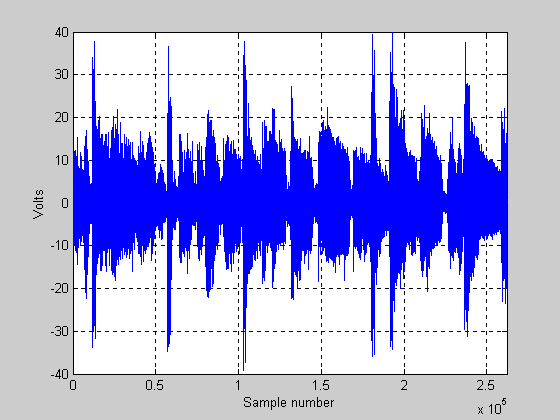
Figure 5.
The signal represented in this plot is that of real music, and it is just at the threshold of clipping for this 100 W amp. One thing that can be seen is that most of the time the signal level is rather low… it is only for very short bursts that the signal reaches the threshold of clipping. These short bursts of high level signal are from bass drums! For the signal above, the amplifier would be delivering 100 watts of power for the largest peaks (those that just reach the + or – 40 volt rail). The RMS voltage (note voltage not power) of the signal in the plot above has a value of 6.4 volts RMS. The “RMS” power (RMS is in quotes because RMS is not really a technically correct term) for this signal is about 5.13 watts! Is this correct? Yes… we have a 100 W amp at the threshold of clipping, and the “average” power being delivered to the speaker is only a little above 5 watts! This is not uncommon for high fidelity music recorded on CD. In this case, the difference between the peak power (100 watts) and the RMS power is about 19.5 times, or about 12.9 dB! This delta is known as crest factor (in this case for power). I am bringing attention to this value as we will show how crest factor diminishes as clipping increases.
Next, we show a plot that shows what things look like when we play the 100 W amp as if it were a 150 W amp. Because we are exceeding the 100 W amp’s capability, the music will be clipped. It will now look like that in Figure 6 below:
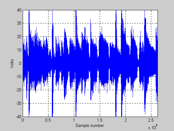
Figure 6.
The signal in Figure 6 does not look terribly different than in Figure 5 above. However, the signal has indeed changed. The RMS voltage of the signal above is now 7.83 volts and the RMS power is 7.66 watts. The crest factor (power) is now approximately 11.2 dB (note that we have compressed the signal by about 1.7 dB by overdriving this amplifier). This makes sense, as a 150 W amp should have about 1.76 dB more power than a 100 W amp.
Next, we show a plot that shows what things look like when we play the 100 W amp as if it were a 400 W amp. Because we are exceeding the 100 W amp’s capability considerably, the music will be clipped pretty badly. It will now look like that in Figure 7 below:
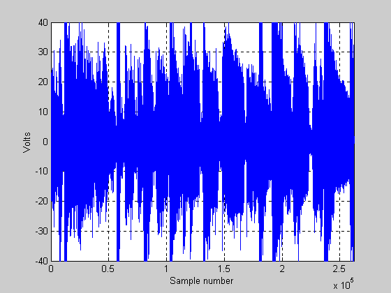
Figure 7.
In this plot it should be pretty obvious that the overall level of the signal is up considerably compared to the first plot where there is no clipping. The RMS voltage of the signal in Figure 7 is now 12.14 volts and the RMS power is 18.4 watts. The crest factor (power) is now approximately 7.35 dB (note that we have compressed the signal by about 5.5 dB by overdriving this amplifier).
Rather than show lots of plots that look similar (for the other amplifiers), the table below shows the numbers that result when a 100W amp is overdriven to the point of trying to act like other amplifiers of various power capabilities:
|
100W Amplifier trying to act like: |
Power Supply Rails |
RMS voltage with music signal (1) |
RMS power with music signal (2) |
Power Crest Factor |
Power Compression |
|
100W |
+/- 40V |
6.40 Vrms |
5.13 W |
12.90 dB |
0 dB |
|
150W |
+/- 49 V |
7.83 Vrms |
7.66 W |
11.16 dB |
1.74 dB |
|
200W |
+/- 56.6 V |
8.97 Vrms |
10.06 W |
9.98 dB |
2.92 dB |
|
300W |
+/- 69.3 V |
10.75 Vrms |
14.44 W |
8.40 dB |
4.50 dB |
|
400W |
+/- 80 V |
12.14 Vrms |
18.41 W |
7.35 dB |
5.55 dB |
NOTES: (1) The value listed in this column (for amps other than the 100 W amp) is the RMS value of the voltage that would result if a 100 W amp was trying to amplify the input signal to the wattage listed in that row. (2) The value listed in this column (for amps other than the 100 W amp) is the RMS value of the power that would result if a 100 W amp was trying to amplify the input signal to the wattage listed in that row.
What does this table tell us? When an amplifier is overdriven into clipping, the peak output power of the amp does not increase, however the average (RMS) power to the speaker does go up. Also, compression of the signal occurs (the amount of compression is a function of how bad the clipping is). Audiophiles strive to maintain the best possible fidelity in music, so clipping an amp is highly intolerable. However, for live music applications (or house parties), amplifiers being driven into clipping is the norm. Although it is not shown in the table, in extreme clipping conditions the RMS power will approach the value of the peak power the amp can deliver. For an amp rated at 100 W RMS, the power output during extreme clipping will approach 200 W (assuming the power supply can keep up).
Some readers might now be asking “What’s the big deal?” The table above shows that I can run my 100 W amp at a level that tries to mimic a 400 W amp and I only increase the average power to the speaker (with this particular music CD) from about 5 watts to about 18 watts! The key thing is this: the music off the CD I used for this analysis has a LOT of dynamic range. Not all music is the same… some types of music have a lot less dynamic range (less crest factor), and when signals like this are overdriven the situation can be a lot more dramatic. Music from an FM radio station is quite compressed compared to a CD, and this would be the type of signal that could really cause problems if driven into clipping. The best advice I can give: avoid situations where more than occasional clipping occurs.
Is clipping bad for an amplifier?: This question is a little off topic for this article, but I'll speak to it briefly. It really depends a lot on how well designed the amplifier is as to whether or not clipping is bad for it. Overall, some minor or occasional clipping is no big deal (in fact most bands and DJs operate this way), but excessive clipping can stress things out. In cases of extreme clipping, operating an amplifier in this fashion might be more likely to stress out (or damage) the power supply as compared to the output semiconductors. Why? When extreme clipping occurs, the output transistors may actually have an easier time (as compared to running at full output with clean music signals) because when extreme clipping occurs they are operating more like a switch, either being fully ON or fully OFF. This means that the output transistors have to deal with less heat dissipation (basically by being fully ON they are sending the vast majority of the power supply's juice to the speakers). Relatively less heat will be dissipated in the transistor in cases of extreme clipping. However, the power supply (consisting of transformer, rectifiers, etc) has to dish out a lot more power than it was likely designed to do (continuously), and if the electronic components used with it were marginally designed or rated to begin with, they could fail. Better amps use components that are more conservatively rated and these amps will be better able to handle the added stress. Amps used for professional touring outfits are often designed to be very rugged in this regard (and of course they cost quite a bit more than amps with similar power ratings that are targeted to the consumer electronic market). Low end amps that use electronic components with bare minimum ratings will be the first to quit when operated in a clipped mode (especially if it is severe clipping). How can you tell if your amp is being stressed out? If it has lighted meters, keep an eye on the light bulbs that light the meters. If they are flickering (going dim when the music is really loud) you are probably at or past the limit of what the amp can safely do. The lights are most likely dimming because the power supply within the amp (which likely powers everything in it) is being "sucked down" by the excessive power being sent to the speakers.
In general, my personal recommendation is to avoid running an amplifier into more than occasional clipping as it can only increase the chances of something bad happening. You could blow speakers, stress out the amp, and if nothing else the sound quality will suffer!
Interpreting Amplifier Specifications: This section explains what various power amplifier specifications mean. We will consider the specifications of the (vintage) Kenwood KA-9100 amplifier:
- Power Output: 90 watts per channel, minimum RMS, at 8 ohms, from 20 Hz to 20,000 Hz with no more than 0.03% total harmonic distortion. This basically means that this amplifier can deliver 90 watts per channel into an 8 ohm load, and it can do it at any frequency between 20 Hz and 20,000 Hz, and the total harmonic distortion will be no more than 0.03%. Although it is not stated, this power is capable of being delivered with both channels operating at 90 watts at the same time. Again, keep in mind that technically there is no such thing as RMS watts; this amplifier basically delivers 90 watts, however it does it using a sine wave signal (not a DC signal)! Note: in reality, almost all amps will put out more than their rated power output. When an amp is rated for power output, the design is such that all production amplifiers will meet this rating. To guarantee that this occurs, the ratings are on the conservative side (otherwise a manufacturer could be accused of "lying" and it would be bad for their reputation). So, most amps will put out at least 10% more power than their actual ratings.
- Both channels driven: 95 +95 watts 8 ohms at 1000 Hz, 110 + 110 watts at 4 ohms at 1000 Hz. This shows that the amp can do a bit better at 1000 Hz (in terms of maximum power output). Most amps do better at mid frequencies with regard to maximum power output. Low frequencies and high frequencies are more demanding and most amps will put out a little less power at these extremes. This spec for the Kenwood also shows the power at 4 ohms.
- Dynamic Power Output: 470 watts at 4 ohms. This is basically showing the limits of what this amp can do (instantaneous power) at 4 ohms. This is total output (from both channels). This amp can do 110 watts per channel continuous RMS at 4 ohms; recall (from above explanations) that the peak power for an amp is twice its RMS rating; so, 220 + 220 = 440. This is not the same as the stated 470 watts; however this basically means that the 110 W RMS rating at 4 ohms had a little bit of conservatism in it, and/or it is for very short bursts of sound that come and go before the power supply rails of the amp can get pulled down by the demand.
- Total Harmonic Distortion: 0.03% at rated power into 8 ohms, 0.01% at 1 watt into 8 ohms. This spec is basically saying that with a pure sine wave as an input signal, the amp will generate no more than 0.03% of distortion as harmonics. So, if the amp is putting out 90 watts, 0.027 watts will be distortion and 89.973 watts will be faithful reproduction. This amount of distortion is vanishingly low in terms of what the human ear can detect. This basically represents a signal that is about 35 dB down from the main signal. Being that this distortion signal is "harmonic distortion" it is a lot more tolerable than (for example) intermodulation distortion. Note that the distortion at 1 watt is a bit lower. This is normal for class AB amps (the Kenwood KA-9100 is one such amp). Class AB amps generally have higher levels of distortion at very low output levels (due to crossover distortion).
- Intermodulation Distortion (60 Hz : 7kHz = 4:1): 0.03% at rated power into 8 ohms, 0.01% at 1 watt into 8 ohms . This is a bit more complicated. Basically, to arrive at this spec two sine wave signals are applied to the amplifier input. In this case, one sine wave was 60 Hz and one was 7000 Hz. The 60 Hz sine wave amplitude was 4 times the amplitude of the 7000 Hz sine wave. This composite signal (which is no longer a simple sine wave) is adjusted in amplitude (keeping the relative ratio of 4:1) until the amp was putting out 90 watts. Then, a frequency analyzer is used to look for frequency lines that are not harmonically related to the two input signals. For example, the frequencies of 120 Hz, 180 Hz, 240 Hz, 300 Hz, etc are ignored. Also ignored are the harmonics of the 7000 Hz signal (these would b 14,000 Hz, 21,0000 Hz, etc). What they do look for in this spec is sum and difference frequencies. for example, frequencies such as 6940 Hz and 7060 Hz would be looked for (for starters), along with any other frequencies that are not harmonics of the main tones. Intermodulation distortion results when two sine waves are applied to a non linear system. Good amplifiers are quite linear (when operated within their design limits), but they are not perfect. All amplifiers will generate some amount of intermodulation distortion. The smaller the number the better, as this kind of distortion is easier for the human ear to detect as compared to harmonic distortion.
- Power bandwidth: 5 Hz to 60,000 Hz. This is the frequency range over which the amplifier can put out substantial amounts of power. Although not mentioned, it is likely that the frequency limits given represent the "half power" points. In other words, the amp can put out (at least) 45 watts at 5 Hz and also at 60,000 Hz. At points in between it will put out more power (the full 90 watts per channel is valid for frequencies of 20 Hz to 20,000 Hz). Basically, the wider the power bandwidth the better, although in some cases an extra wide band can lead to problems.
- Frequency Response: DC to 100,000 Hz, +0 dB, - 1dB. This shows the frequency response of the amplifier, but it does not mention the power at which it was measured (so we have to assume it is probably 1 watt or some other small value). It is definitely not at full output of this amp. Why DC? This amp uses DC coupled stages within it. Not all amps do this, and in general it is not needed to have great sound.
- Signal to Noise Ratio: 115 dB (short circuited). This is a pretty important spec. It is measured by putting a short circuit at the input (certainly not the output!) of the amplifier, and then measuring the noise at the output. Although it is not mentioned, this is almost certainly what is called an "A" weighted noise measurement (as compared to a "C" weighted measurement). A "C" weighting measurement is basically no weighting (adjustment curve) at all, it is a "full band" noise measurement (from 20 Hz - 20,000 Hz). "A" weighting is basically a measurement that is used to make the measurement more akin to what the human ear hears. Human hearing is not as sensitive at frequency extremes, so noise (for example) that is very low in frequency or very high in frequency does not sound as loud as noise at mid band frequencies. The "A" weighting curve (measurement) tries to take this into account. "C" weighting measurements would have lower numbers (for example instead of 115 dB it might be 109 dB). "C" weighting numbers do not look as good. So far as I know most amps (those used for amplifying music) are rated for signal to noise ration using A weighting. Make sure you compared amps based on the same measurement scale or one will seem to be a lot better than another when in fact they might be the same! What does a rating of -115 dB mean? Basically that the sound level of the output noise of the amplifier would sound (to the human ear) to be 115 dB quieter than the signal the amp can generate at full power. You'd NEVER hear such noise with many kinds of music (when the music is being played at or near the limits of the amplifier's power capability. The exception is possibly classical music, a type of music that has very quiet passages mixed n with very loud passages. Amplifiers can only be so quiet, there is no (practical) way to make a noiseless amplifier.
- Damping factor: 50 at 8 ohms. Damping factor is basically a measure of the output impedance of the amplifier. High numbers are better.
- Input Sensitivity/Impedance: 1.0 V / 50 k ohms. This specification shows home much voltage must be applied to the input of the amplifier (into a load impedance of 50,000 ohms) in order to get the full rated output. If more signal than this is applied, the amp will clip with the volume control all the way up. If less than this amount of signal is applied, the amp will not reach full output capability. This number is important when considering what the previous stage can deliver (a preamp for example). The prior stage should be able to deliver at least this amount of voltage (preferably more).
- Speaker Impedance: Accept 4 to 16 ohms. Nothing too hard here, it basically states that speakers with impedance anywhere from4 to 16 ohms will work.
Items below are topics I intend to add when time allows!
DC to speakers when clipping???: Things to write about: sometimes
Slew Rate???: What the heck is a slew rate and how does it relate to amplifier performance?
Discuss 8 ohm and 4 ohm (and 2 ohm) power ratings???: Things to write about: relate to power supply limits, overall design of amp, etc.
What is crest factor???: Things to write about: 3 dB for sine wave, around 8 dB for random noise (verify using MATLAB), more for high fidelity CD music.
What is dynamic headroom???: Things to write about: ability of amp to put out more power for a short time due to a loosely regulated power supply; amps with tightly regulated supplies have little or no dynamic headroom
Are amplifiers with dual power supplies better than those with only one supply???: Things to write about: Yes.... Maybe... if they are designed well and if the wall socket can deliver the needed juice!
Why do most amplifiers have relatively higher distortion when the output is low???: Things to write about: crossover distortion
How do I calculate the power output for music signals???: Things to write about: RMS or area under curve
ARTICLE TO BE CONTINUED, THIS IS A PARTIAL WORKING DRAFT!
Below here is the MATLAB M-file I wrote to do some of the analysis on the music signal. It is not well commented as I threw it together in a hurry.
%%%%%%%%%%%% 22 Jan 2005 J. Roberts %%%%%%%%%%%%%%%%%%%%%%%%%%%%%%%%%%%%%%%%
%ch2 is the raw music data recorded using Magix, has already been converted to MAT file using original WAV file.
% we will normalize this data so that it peaks at the rails of a particular amp.
%We use a 100 watt amp with rails of 40 volts
%truncate ch2 data to length 262144 (2^18) for easy FFTs later on
ch2=ch2(1:262144);
%normalize the data
ch2n=ch2/(max(abs(ch2))); % normalizes data to a peak value of 1
%now amplify data so that it peaks at rails of a 100 w amp
ch2n=ch2n.*40; % this is the signal we'd see at the output of a 100 W (rms) amp!
%Now generate data for various levels of other amps
% for a 150 W amp (rails are 49 volts)
ch2n_150=ch2n.*(49/40);
% for a 200 W amp (rails are 56.57 volts)
ch2n_200=ch2n.*(56.57/40);
%For a 300 W amp (rails =69.3 v):
ch2n_300=ch2n.*(69.3/40);
%For a 400 W amp (rails =80 v):
ch2n_400=ch2n.*(80/40);
%Now we have to adjust the amps stronger than 100 W so that the data clips at 100W output (40 volts).
100
%First do the positive voltages for the 150 watt case:
for c=1:262144;
if(ch2n_150(c))>40;
ch2n_150(c)=40;
end
end
% then do the negative voltages:
for c=1:262144;
if(ch2n_150(c))<-40;
ch2n_150(c)=-40;
end
end
200
%First do the positive voltages for the 200 watt case:
for c=1:262144;
if(ch2n_200(c))>40;
ch2n_200(c)=40;
end
end
% then do the negative voltages:
for c=1:262144;
if(ch2n_200(c))<-40;
ch2n_200(c)=-40;
end
end
300
%First do the positive voltages for the 300 watt case:
for c=1:262144;
if(ch2n_300(c))>40;
ch2n_300(c)=40;
end
end
% then do the negative voltages:
for c=1:262144;
if(ch2n_300(c))<-40;
ch2n_300(c)=-40;
end
end
%First do the positive voltages for the 400 watt case:
for c=1:262144;
if(ch2n_400(c))>40;
ch2n_400(c)=40;
end
end
% then do the negative voltages:
for c=1:262144;
if(ch2n_400(c))<-40;
ch2n_400(c)=-40;
end
end
% Now calculate some RMS voltage values and power values for the signals using the RMS voltages
% also calculate crest factor for voltage and power
% vx = RMS voltage
% px = RMS power
% v_crest=voltage crest factor
% p_crest=power crest factor
vx_100=std(ch2n)
px_100=(std(ch2n)*std(ch2n))/8 % 8 is for 8 ohms
v_crest_100=20*log10(40/vx_100)
p_crest_100=10*log10(100/px_100)
vx_150=std(ch2n_150)
px_150=(std(ch2n_150)*std(ch2n_150))/8 % 8 is for 8 ohms
v_crest_150=20*log10(40/vx_150)
p_crest_150=10*log10(100/px_150)
vx_200=std(ch2n_200)
px_200=(std(ch2n_200)*std(ch2n_200))/8 % 8 is for 8 ohms
v_crest_200=20*log10(40/vx_200)
p_crest_200=10*log10(100/px_200)
vx_300=std(ch2n_300)
px_300=(std(ch2n_300)*std(ch2n_300))/8 % 8 is for 8 ohms
v_crest_300=20*log10(40/vx_300)
p_crest_300=10*log10(100/px_300)
vx_400=std(ch2n_400)
px_400=(std(ch2n_400)*std(ch2n_400))/8 % 8 is for 8 ohms
v_crest_400=20*log10(40/vx_400)
p_crest_400=10*log10(100/px_400)
plot(ch2n_400, 'b')
hold
plot(ch2n_300, 'r')
plot(ch2n_200, 'g')
plot(ch2n_150, 'y')
plot(ch2n, 'k')